> ## Documentation Index
> Fetch the complete documentation index at: https://omi-codex-chat-first-ui-plan.mintlify.site/llms.txt
> Use this file to discover all available pages before exploring further.

# Building the Device

> Step-by-step guide to assemble your own Omi device from parts.

## Before You Start

<CardGroup cols={2}>
  <Card title="Parts List" icon="list-check" href="/doc/assembly/Buying_Guide">
    Make sure you have all required components
  </Card>

  <Card title="3D Print Case" icon="cube" href="https://github.com/BasedHardware/omi/tree/main/omi/hardware/triangle%20v1">
    Download and print the case STL files
  </Card>
</CardGroup>

<Tip>
  If you don't have access to a 3D printer, check [Makerspace.com](https://makerspace.com/) for printing locations near you, or use an online 3D printing service.
</Tip>

***

## Assembly Instructions

<Steps>
  <Step title="Prepare the Components">
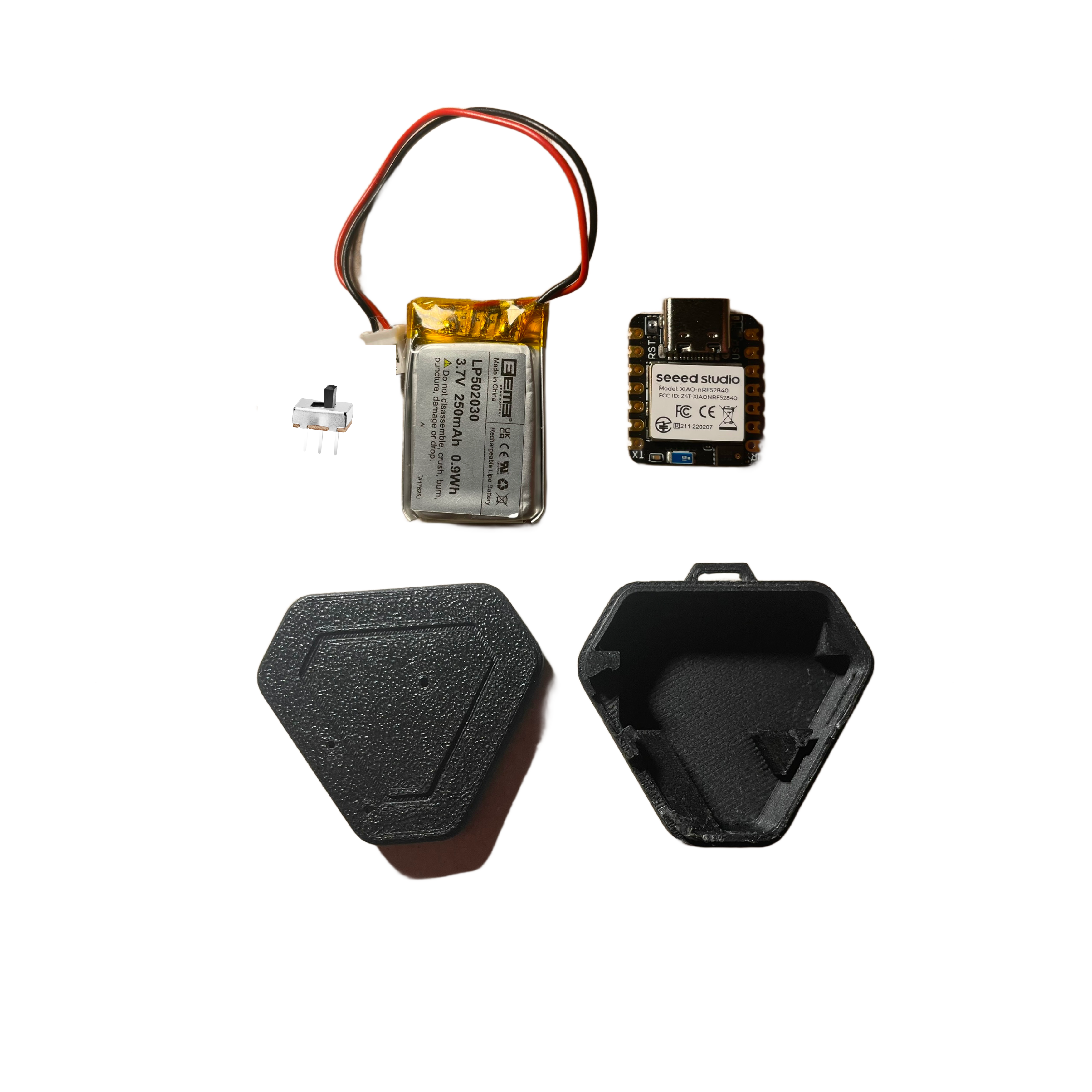
    Gather all your parts: XIAO board, battery, switch, wires, and 3D printed case.
    <Frame>
      <img src="https://mintcdn.com/omi-codex-chat-first-ui-plan/onfmnUfA9EvkxmE6/images/docs/assembly/images/latest_assembly/components.png?fit=max&auto=format&n=onfmnUfA9EvkxmE6&q=85&s=ba44727756ad7bf5430ed8f2ef8fbfca" alt="All components laid out" width="3500" height="3500" data-path="images/docs/assembly/images/latest_assembly/components.png" />
    </Frame>
  </Step>

  <Step title="Cut the Black Wire">
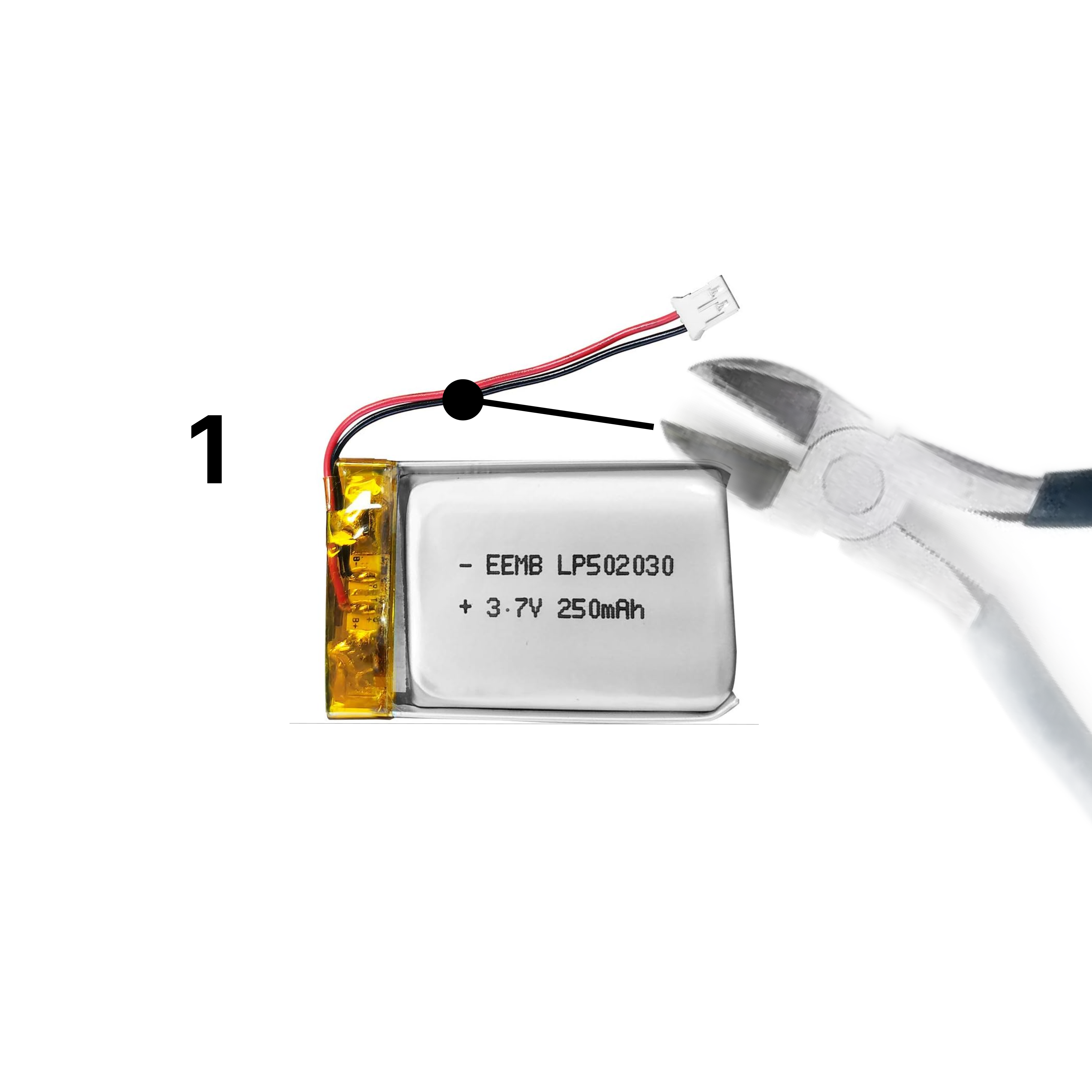
    Cut the black wire approximately **2/3 inch (17mm)** from the base of the battery connector.
    <Frame>
      <img src="https://mintcdn.com/omi-codex-chat-first-ui-plan/onfmnUfA9EvkxmE6/images/docs/assembly/images/latest_assembly/1.png?fit=max&auto=format&n=onfmnUfA9EvkxmE6&q=85&s=2032b142ae5f17ee99f619cbc5ba6670" alt="Cutting the black wire" width="3500" height="3500" data-path="images/docs/assembly/images/latest_assembly/1.png" />
    </Frame>
  </Step>

  <Step title="Strip the Wire Ends">
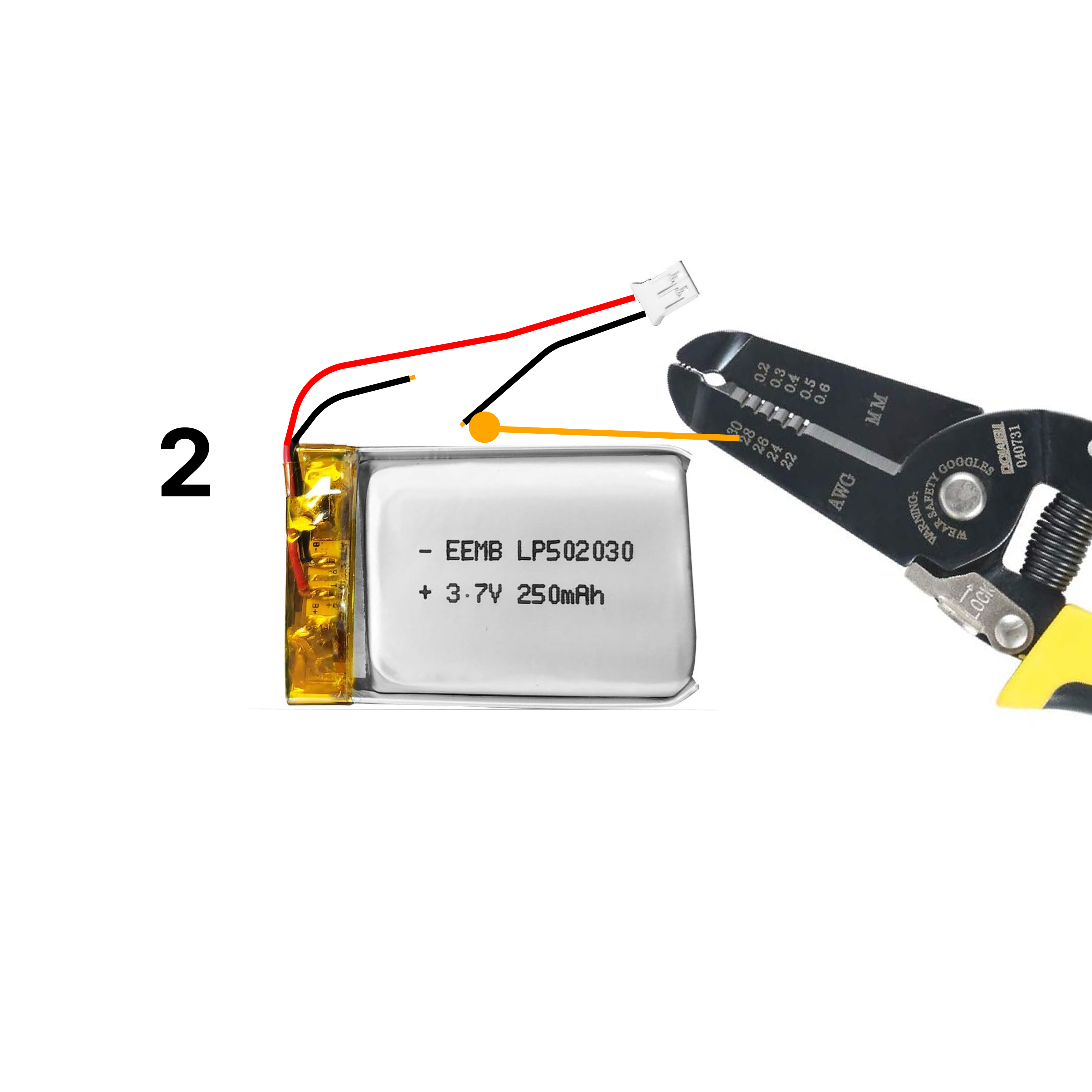
    Remove a small portion of insulation from both ends of the cut wire using a wire stripper.

    <Note>
      Use the **28 AWG** notch on your wire stripper for best results.
    </Note>

    <Frame>
      <img src="https://mintcdn.com/omi-codex-chat-first-ui-plan/onfmnUfA9EvkxmE6/images/docs/assembly/images/latest_assembly/2.png?fit=max&auto=format&n=onfmnUfA9EvkxmE6&q=85&s=8392180eb66c3e802021fca7c8960ffa" alt="Stripped wire ends" width="3500" height="3500" data-path="images/docs/assembly/images/latest_assembly/2.png" />
    </Frame>
  </Step>

  <Step title="Solder the Components">
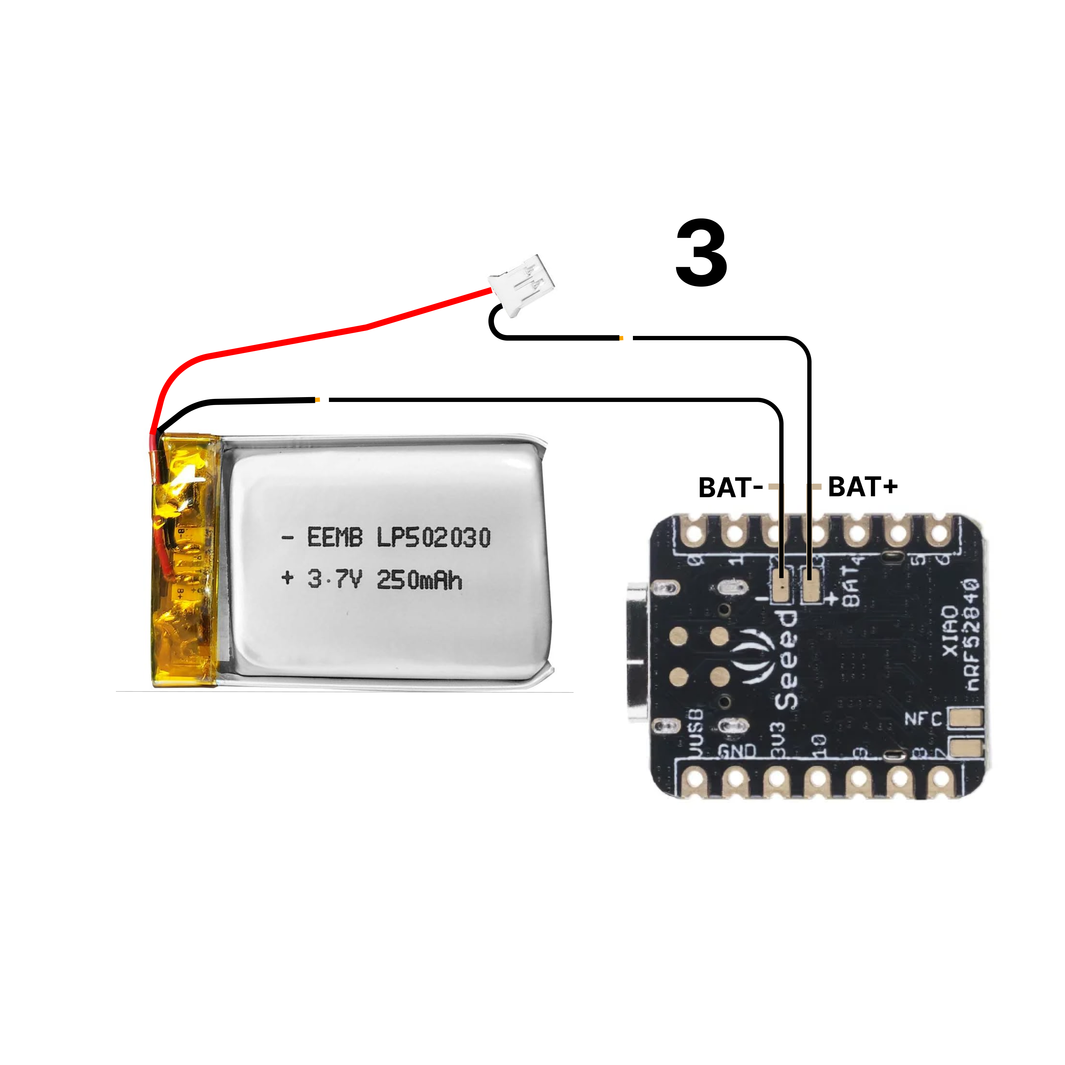
    Follow the soldering diagram to connect the battery to the board. The switch goes in-line with the black (ground) wire.
    <Frame>
      <img src="https://mintcdn.com/omi-codex-chat-first-ui-plan/onfmnUfA9EvkxmE6/images/docs/assembly/images/latest_assembly/3.png?fit=max&auto=format&n=onfmnUfA9EvkxmE6&q=85&s=0c25f932d4e769343eca243675d2e7d8" alt="Soldering diagram" width="3500" height="3500" data-path="images/docs/assembly/images/latest_assembly/3.png" />
    </Frame>

    <Warning>
      Be careful with soldering! Use proper ventilation and safety equipment.
    </Warning>
  </Step>

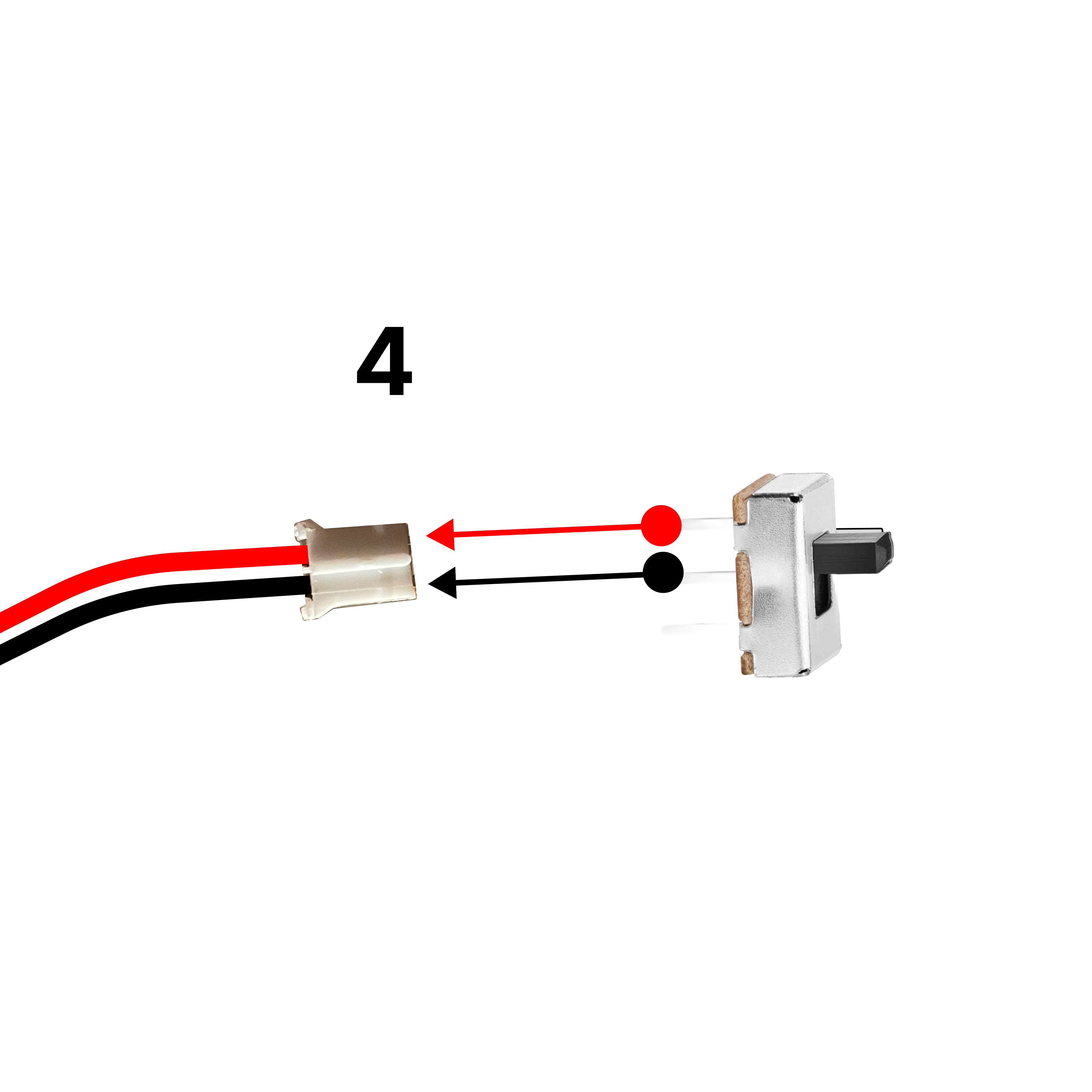
  <Step title="Secure the Switch">
    Insert the switch securely into the battery connector circuit.
    <Frame>
      <img src="https://mintcdn.com/omi-codex-chat-first-ui-plan/onfmnUfA9EvkxmE6/images/docs/assembly/images/latest_assembly/4.png?fit=max&auto=format&n=onfmnUfA9EvkxmE6&q=85&s=a744af1ec9fe597497eeadfc2241ae26" alt="Switch secured" width="3500" height="3500" data-path="images/docs/assembly/images/latest_assembly/4.png" />
    </Frame>
  </Step>

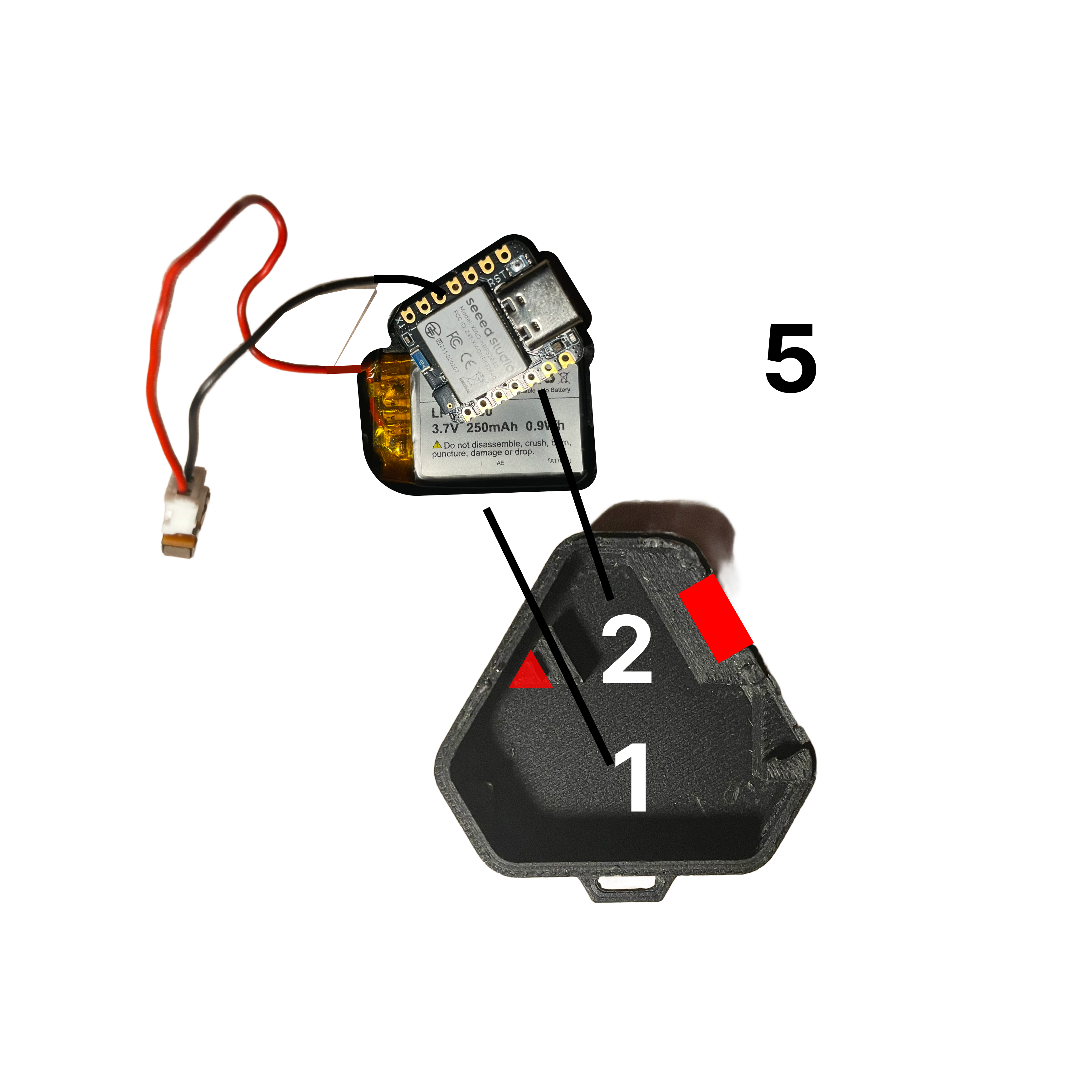
  <Step title="Place Battery and Board in Case">
    Carefully place the battery and board into the 3D-printed case.
    <Frame>
      <img src="https://mintcdn.com/omi-codex-chat-first-ui-plan/onfmnUfA9EvkxmE6/images/docs/assembly/images/latest_assembly/5.png?fit=max&auto=format&n=onfmnUfA9EvkxmE6&q=85&s=2c8d5bc131b110d0fb8e4b7551e23188" alt="Components in case" width="3500" height="3500" data-path="images/docs/assembly/images/latest_assembly/5.png" />
    </Frame>
  </Step>

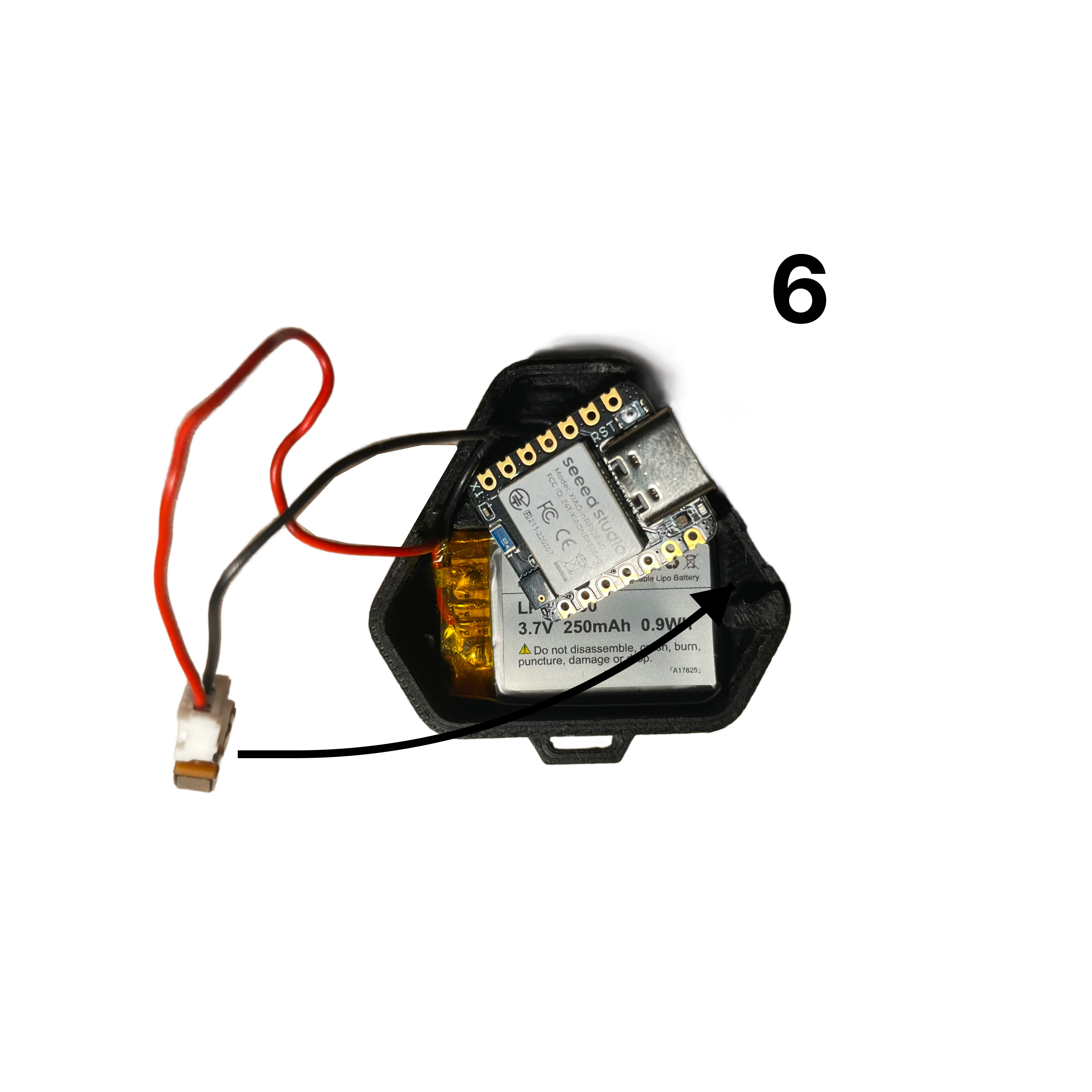
  <Step title="Position the Switch">
    Insert the switch into the notch next to the USB-C slot.
    <Frame>
      <img src="https://mintcdn.com/omi-codex-chat-first-ui-plan/onfmnUfA9EvkxmE6/images/docs/assembly/images/latest_assembly/6.png?fit=max&auto=format&n=onfmnUfA9EvkxmE6&q=85&s=d4e18c9106583ca725651b9f2d8cb880" alt="Switch in notch" width="3500" height="3500" data-path="images/docs/assembly/images/latest_assembly/6.png" />
    </Frame>
  </Step>

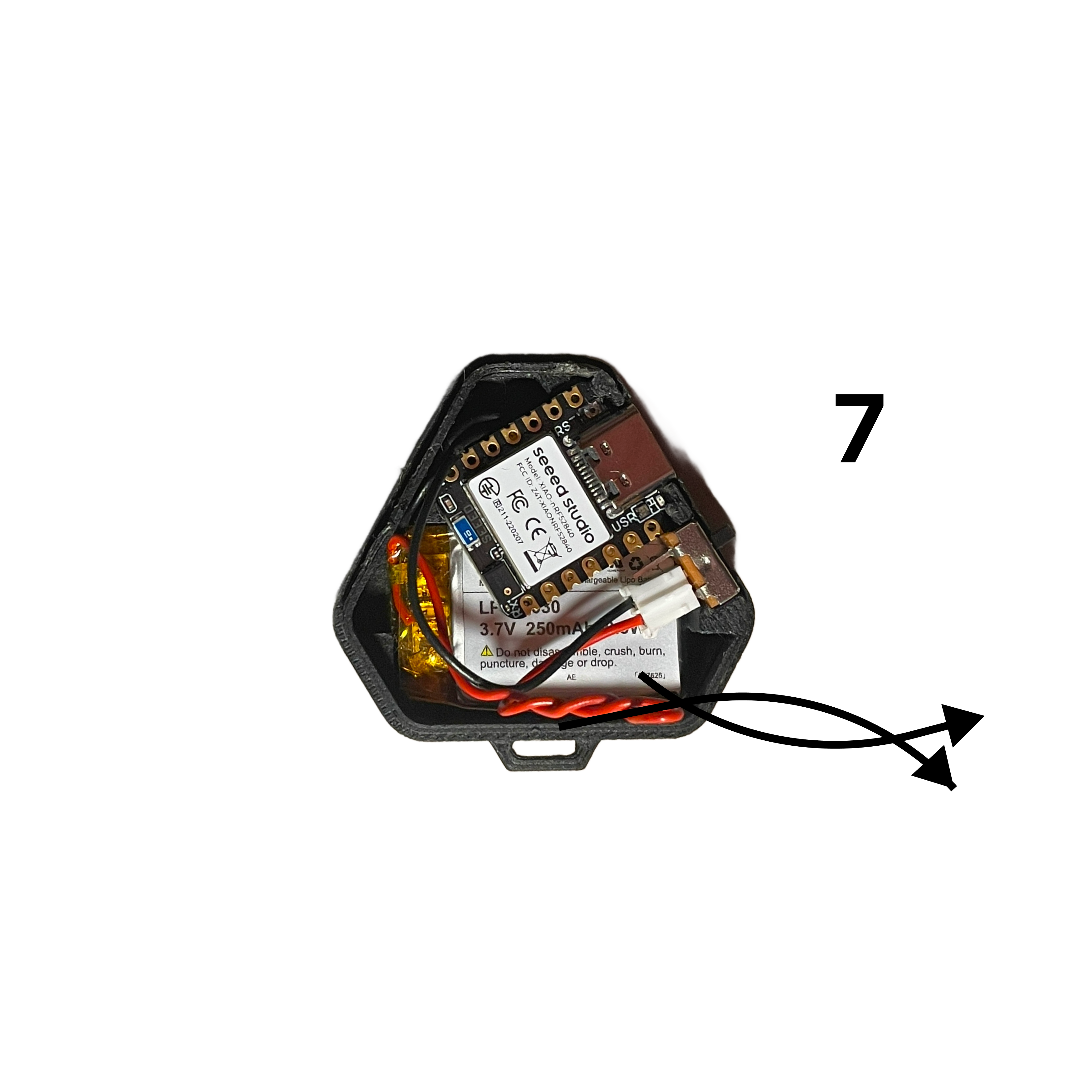
  <Step title="Manage the Wires">
    Twist the longer red wire gently to help organize it within the case.
    <Frame>
      <img src="https://mintcdn.com/omi-codex-chat-first-ui-plan/onfmnUfA9EvkxmE6/images/docs/assembly/images/latest_assembly/7.png?fit=max&auto=format&n=onfmnUfA9EvkxmE6&q=85&s=3a2dccb66f3aee83740ea1d790123178" alt="Twisted wire" width="3500" height="3500" data-path="images/docs/assembly/images/latest_assembly/7.png" />
    </Frame>
  </Step>

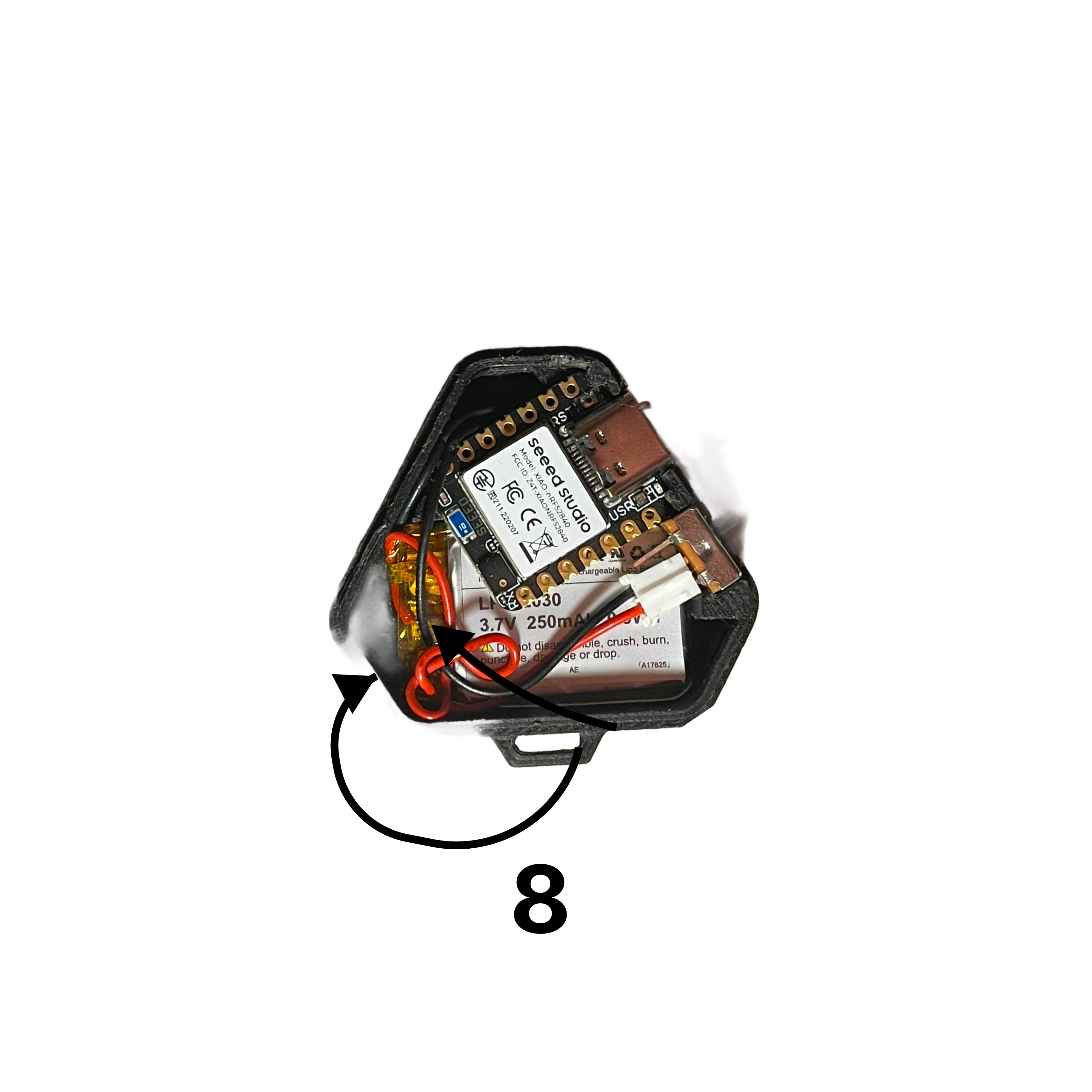
  <Step title="Curl the Wire">
    Carefully curl the twisted wire and place it to the side to ensure it fits within the case.
    <Frame>
      <img src="https://mintcdn.com/omi-codex-chat-first-ui-plan/onfmnUfA9EvkxmE6/images/docs/assembly/images/latest_assembly/8.png?fit=max&auto=format&n=onfmnUfA9EvkxmE6&q=85&s=328efaaf3716a46f83c030640b574f61" alt="Curled wire placement" width="3500" height="3500" data-path="images/docs/assembly/images/latest_assembly/8.png" />
    </Frame>
  </Step>

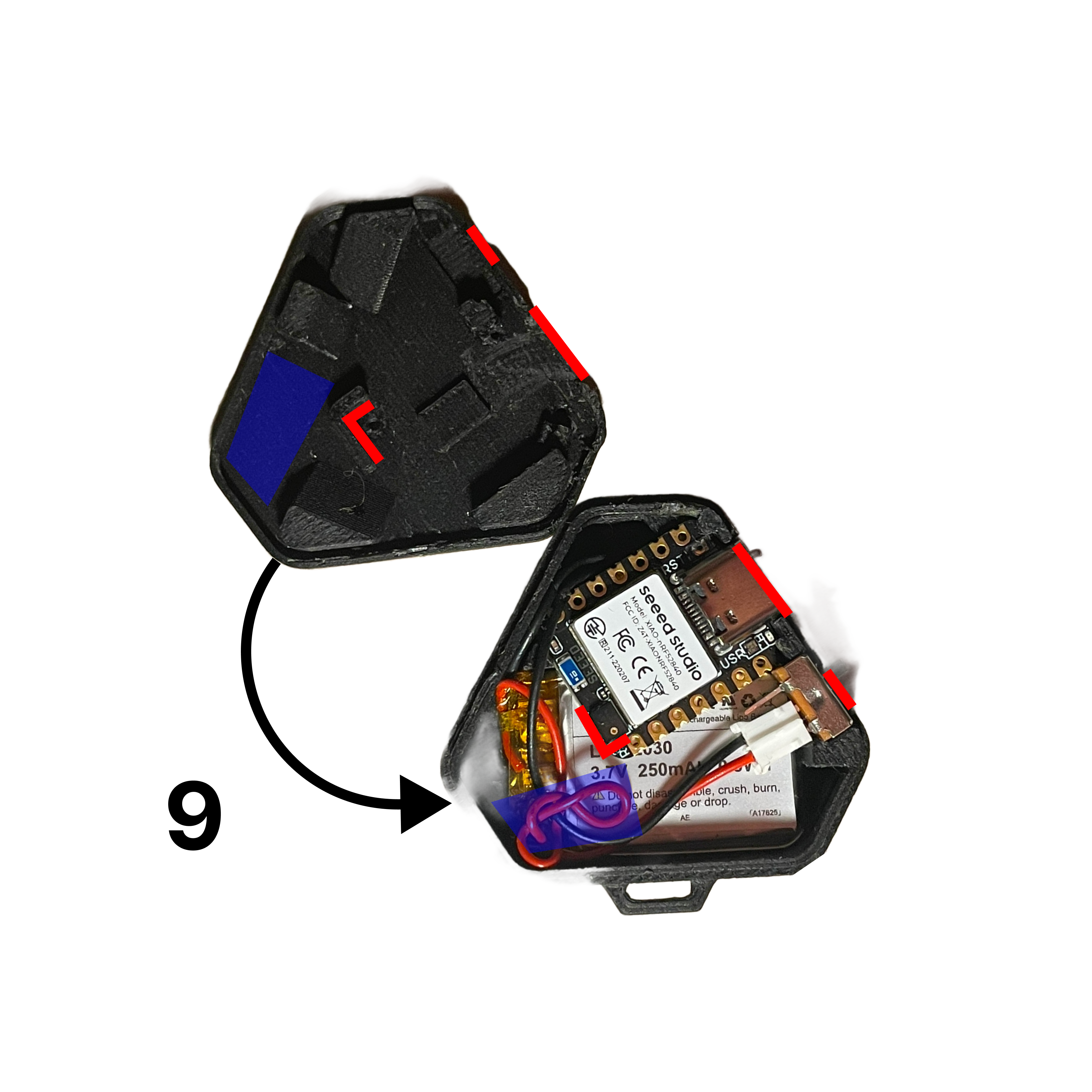
  <Step title="Attach the Lid">
    Align the lid with the case using the ridges as a guide and snap it into place.
    <Frame>
      <img src="https://mintcdn.com/omi-codex-chat-first-ui-plan/onfmnUfA9EvkxmE6/images/docs/assembly/images/latest_assembly/9.png?fit=max&auto=format&n=onfmnUfA9EvkxmE6&q=85&s=640a35163e7eb6467526455dd9521717" alt="Attaching the lid" width="3500" height="3500" data-path="images/docs/assembly/images/latest_assembly/9.png" />
    </Frame>
  </Step>

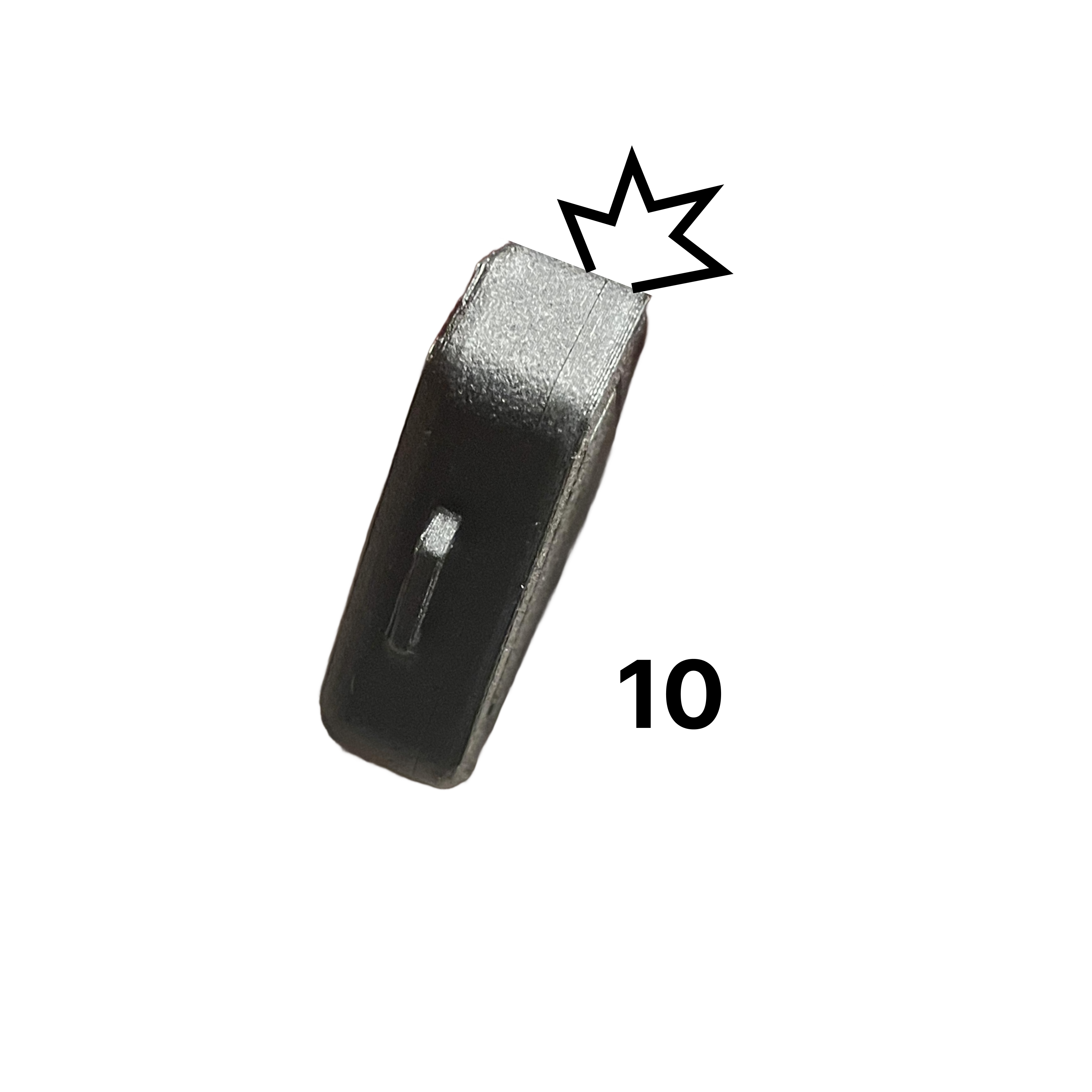
  <Step title="Secure the Case">
    Apply even pressure around the edges to ensure the seams snap securely into place.
    <Frame>
      <img src="https://mintcdn.com/omi-codex-chat-first-ui-plan/onfmnUfA9EvkxmE6/images/docs/assembly/images/latest_assembly/10.png?fit=max&auto=format&n=onfmnUfA9EvkxmE6&q=85&s=8585f21d83924dff1ba8988265db23b9" alt="Secured case" width="3500" height="3500" data-path="images/docs/assembly/images/latest_assembly/10.png" />
    </Frame>
  </Step>
</Steps>

***

## Charging Instructions

<Warning>
  **Important:** Omi can only charge when it is powered **ON**. The device will not charge if powered off.
</Warning>

* Use a standard USB-C cable to charge
* The LED will indicate charging status
* A full charge takes approximately 1-2 hours

***

## Congratulations!

You now have a fully assembled Omi device!

<CardGroup cols={2}>
  <Card title="Flash Firmware" icon="bolt" href="/doc/get_started/Flash_device">
    Install the latest firmware on your device
  </Card>

  <Card title="Set Up the App" icon="mobile" href="/doc/get_started/introduction">
    Download and configure the Omi app
  </Card>

  <Card title="Get Support" icon="wrench" href="/doc/info/Support">
    Having issues? Get help from our community or contact support
  </Card>

  <Card title="Join Community" icon="discord" href="http://discord.omi.me">
    Get help from the community on Discord
  </Card>
</CardGroup>
